They are lines with pointed edges at one or both ends. What does a orthographic projection show.
![]()
Orthographic Projection Multi View Drawing Ppt Video Online Download
5-10 view B to the right of the top view at a convenient distance keeping the appearance of a balanced drawing.

. 5-10 view C then vertically downward fig. Example Start with the front view The edge C cannot be seen but is. This line is similar to the Dash Thin Lines with Dots except that it has double dots within it.
Place the miter line fig. Arrowhead Lines are used. A Miter Bend or Miter Elbow is prepared by mitering angle cutting and welding pipe ends of the cut-pieces usually at a 45 and 90 to form a corner.
Figure 34 Engineering drawing line types A to K ISO 1281982 leader lines cross hatching outlines of revolved sections short centre lines thread routes and symmetry equals signs. The length of the long dashes varies according to the size of the drawing and is approximately 20 to 40 mm. What is a Miter Bend.
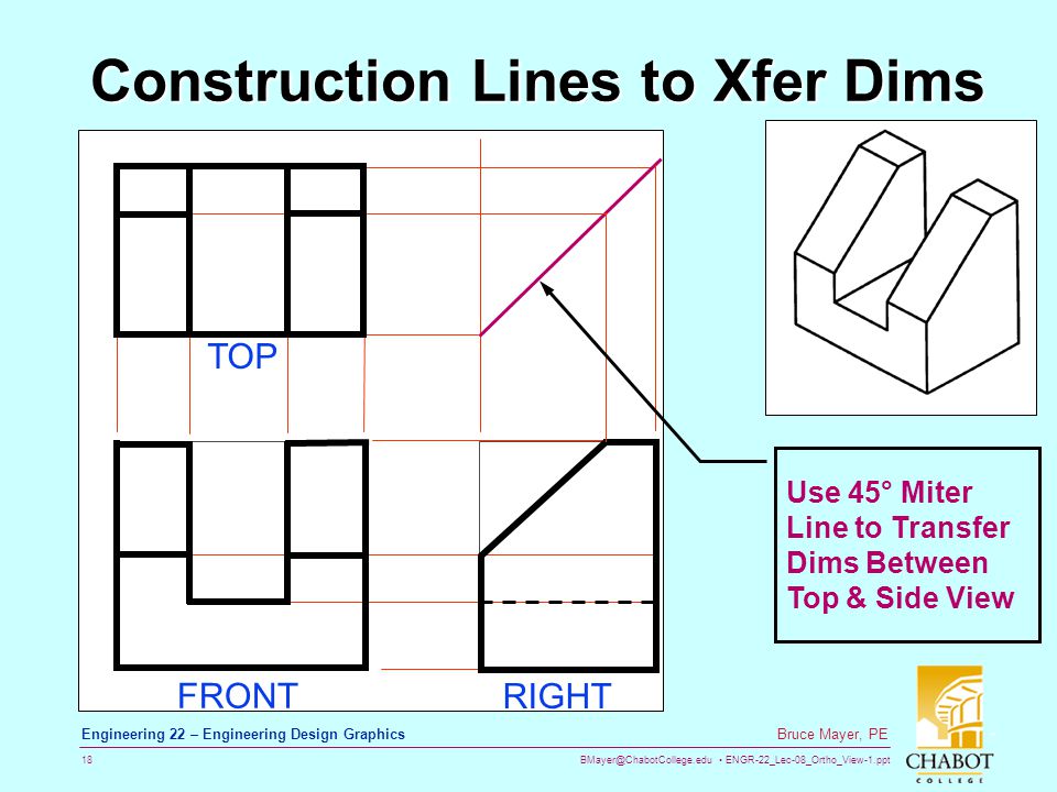
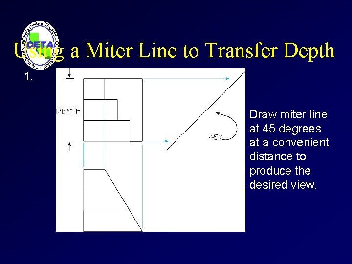
Page 113 Yoke Orthographic Projection Tutorial Contents click to go to that section Starting the Drawing Drawing the Views The Miter Line and Orthographic Projection Center Lines Linetype Scale Hidden Lines Dimensioning Editing Dimensions. The Miter Line and Projection Lines The use of a 45 miter line and Projection Lines provide a quick accurate method of drawing the other views once one view is completed. Orthographic Views and Multiview Constructions 4-33 Drawing using the Miter Line method The 45 miter line method is a simple and straightforward procedure to transfer measurements between the top view and the side view.
It is obvious that a top view of this object tells you everything you need to know except the. The 45 miter line starts at the intersection of lines 1 and 2. Visible Line Hidden Line Cutting-Plane Lines Center Line.
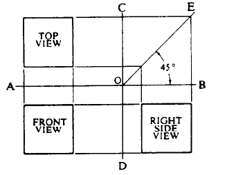
Place the miter line OE to the right of the top view at a convenient distance keeping the appearance of a balanced drawing. Two widths of lines are typically used on drawings. The Miter Line and Projection Lines.
What is a Miter line in engineering drawing. On your own use the Offset and Trim commands and modify the top view as shown. The pointed edges are in the form of an arrow.
Miter ElbowBend is made from miter cut pieces of pipeThe Miter pieces also called gores There are two end. The ISO type C lines are thin wavy and continuous as shown in Figure 37. Lines 1 and 2 radiate from the edge views EV of the frontal planes in the top and right views.
A miter line OE in the figure offers a convenient method of laying out a third view while you are in the process of drawing two views. Sometimes you will need to work on separate views and project lines to each other to fully complete any view. 14 Engineering Drawing MCQs and Answers Set-IV.
12 Engineering Drawing MCQs and Answers Set-II. One and Two-View Drawings. 15 Engineering Drawing MCQs and Answers Set-V.
Whatever area you will. It is often the case that a two-view projection is all that is required. 11 Engineering Drawing MCQs and Answers Set-I.
It is used for ghost outlines and bend. Example Represent the shown component using multiple view representation. I have always been intrigued by exploded axonometric illustrations.
Place the miter line OE to the right of the top view at a convenient distance keeping the appearance of a balanced drawing. What type of drawing do we use the miter line. For general engineering drawings the types of lines recommended by the Bureau of Indian Standards shown in table 2 must be used.
Engineering Drawing WELCOME TO. Draw light projection lines from the top view to the miter line fig. For a very large section view drawing the long dashes are made very long to save drawing time.
Figure 34 Engineering drawing line types A to K ISO 1281982. The thick line width should be 06 mm and the thin line width should be 03 mm. Place the miter line OE to the right of the top view at a convenient distance keeping the appearance of a balanced drawing.
Line B-B is composed of alternating long and two short dashes which is one of the two standard methods. In technical Engineering drawings each line has a definite meaning and is drawn in accordance to the line conventions as illustrated in the figure below. Newbie drafters will sometimes try to avoid using the.
5-19 Two View Projections. The thickness of the lines must be chosen according to the type and size of the drawing from any of the six groups given in Table 1. NWP June 2007 Version 05 100 Fundamental of Engineering Drawing - ขนตอนท 3 การเลอกภาพด านข าง adjacent view จากตวอย างของการสร างภาพออโธกราฟ กด วยกล องแก ว.
Miter line is used to ensure the alignment of the three views. Orthographic Projection utilizes a Miter Line drawn at 45 degrees which enables information to be projected from the top view to the side view and from the side view to the top view. A miter line OE in the figure offers a convenient method of laying out a third view while you are in the process of drawing two views.
At the end of dimensional lines. 5-10 offers a convenient method of laying out a third view while you are in the process of drawing two views. A miter line OE in the figure offers a convenient method of laying out a third view while you are in the process of drawing two views.
16 Engineering Drawing MCQs and Answers Set-VI. There are two types of miter bend one non-perpendicular bend another is 3-D bend. Using the 45 miter line makes it both.
The use of a 45 miter line and Projection Lines provide a quick accurate method of drawing the other views once one view is completed. Line convention The meaning of lines in Orthographic Drawings TOPICS continued Working Drawings Scaled Drawings Dimensioning Drawing with a Miter Line Practice Worksheets Working Drawings The final stage of illustrating your solution is to prepare a set of technical illustrations called Working Drawings. Line 4 5 and 6 help transfer the hole from the top to the right view.
A miter line fig. 1 What type of sketch uses a miter line. Line 3 helps transfer the small notch from the right to the top view.
Sometimes you will need to work on separate views and project lines to each other to fully complete any view. The view at the top of figure 5-19 shows a single-view projection of an object. What is an exploded axonometric.
13 Engineering Drawing MCQs and Answers Set-III. See the FUNDAMENTALS OF ENGINEERING GRAPHICS Textbook.
Orthrographic View Dwgs 1 Ppt Video Online Download
Orthographic Projection Multiview Drawing Orthographic Projection A System

Orthographic Projection
2
![]()
Orthographic Projection Multi View Drawing Ppt Video Online Download

Orthographic Projection
2
Using A Miter Line Manufacturinget Org
0 comments
Post a Comment